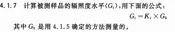
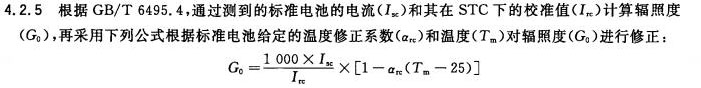
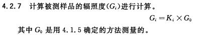
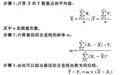
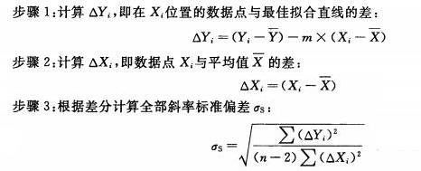
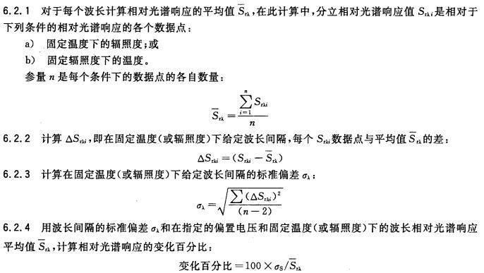
1 Scope This part of GB/T 6495 specifies a linear characteristic program for determining any parameter of a photovoltaic device with test parameters, which is mainly used by calibration laboratories, component manufacturers, and system designers. The evaluation of the properties of photovoltaic modules and systems can be achieved by using linear equations, and the characteristics under one set of temperature and irradiance conditions can also be derived to calculate the characteristics under another set of conditions (see GB/T 6495.4 and GB/T 18210). ). This section establishes linear characteristic requirements and test methods that ensure satisfactory results for the linear equations. These requirements define the range of temperature and irradiance variations to which this linear equation can be applied. The measurement methods described in this section apply to all photovoltaic devices and can be applied to samples or comparable devices under the same technology. It should be used before all the test and correction procedures required for a linear device. The method used in this section is similar to the linear function defined in GB/T 6495.4. This linear (linear) function is obtained by fitting a set of data points using a least-squares fitting calculation. Data changes from this function can also be calculated and the deviation of the linearity expressed as a percentage of the allowable change. The linear characteristics of a photovoltaic device are only taken into consideration when the following temperature and irradiance range conditions of interest are met. The typical minimum temperature range is from 25°C to 60°C, and the minimum irradiance range is from 700W·m-2 to 1000W·m-2. a) for the short-circuit current curve with respect to changes in irradiance, the normalized slope standard deviation (σs/m) is less than 0.02; b) the standard deviation of the normalized slope (σs/m) is less than 0.05 for the open-circuit voltage curve with respect to the logarithm of the irradiance; c) the normalized slope standard deviation (σs/m) is less than 0.1 for the open circuit voltage and short circuit current curves with respect to temperature changes; d) The relative spectral response of a certain wavelength range at a specific voltage varies by less than 5%. Note 1: Many IEC photovoltaic standards require spectral mismatch corrections for spectral response measurements. Therefore, the linear characteristics of the spectral response with respect to temperature and irradiance are important. This is important for some new technologies such as photochemical batteries. Note 2: Since the relative spectral response of some devices, such as amorphous silicon solar cells, varies greatly with voltage, it is important to determine the linear characteristics at the bias voltage. The choice of voltage value is determined by the final usage. If the area of ​​concern is the maximum power condition, Vmax can be chosen; if it is for correction, the zero bias voltage is more appropriate. Note 3: It should be noted that the relative spectral response of some devices varies with temperature and irradiance. Some of these effects, such as changes in items a) and c), can be considered nonlinearly for short-circuit currents, while others are not. In the case of item d), nonlinearity (short-circuit current) needs to be considered. For these and other performance parameters, the general procedure for determining their linear characteristics is in Chapter 4, Chapter 6. 2 normative references The following documents are indispensable for the application of this document. For dated references, only dated versions apply to this document. For undated references, the latest edition (including all amendments) applies to this document. GB/T 6495.2-1996 Photovoltaic devices - Part 2: Requirements for standard solar cells (idt IEC 60904-2:1989) GB/T 6495.3-1996 Photovoltaic devices - Part 3: Measurement principles and standard spectral irradiance data for ground-based photovoltaic devices (idt IEC 60904-3: 1989) GB/T 6495.4-1996 Temperature and irradiance correction methods for measured IV characteristics of crystalline silicon photovoltaic devices (idt IEC 60891:1987) GB/T 6495.7-2006 Photovoltaic devices - Part 7: Calculation of spectral mismatch errors caused by measurement of photovoltaic devices GB/T 6495.10-2012/IEC 60904-10:1998 (IEC 60904-7:1998, IDT) GB/T 6495.8-2002 Photovoltaic devices-Part 8: Spectral response of photovoltaic devices (IEC 60904-8:1998, IDT) GB/T 6495.9-2006 Photovoltaic devices - Part 9: Solar simulator performance requirements (IEC 60904-9:1995, IDT) GB/T 18210-2000 In-situ measurement of IV characteristics of crystalline silicon photovoltaic (PV) quadrants (IEC 61829:1995, IDT) GB/T 18911-2002 Design and identification of thin-film photovoltaic modules for use on the ground (IEC 61646:1996, IDT) SJ/T 11209-1999 Photovoltaic devices - Part 6: Requirements for standard solar modules (IEC 60904-6:1994, IDT) IEC 61215:1993 Crystalline silicon photovoltaic (PV) module design qualification and type approval (Crystalline silicon terrestrial photovoltaic (PV) modules-Design qualification and type approval) 3 Instruments 3.1 Test Instruments Use the following instrument controls and side volume side test environments: a) A test light source (natural light or a solar simulator conforming to the requirements of GB/T 6495.9, class B or better than class B). b) Any instrument that changes the irradiance within the range of interest, without affecting the relative spectral radiometric distribution and spatial uniformity, such as a light reduction network or a neutral filter. Note: Equipment and procedures for changing irradiance need to be radiometrically verified. Changes in the relative spectral irradiance distribution affect the short-circuit current variation of the standard battery by no more than 0.5% (see GB/T 6495.7 and GB/T 6495.8). It is acknowledged that the light reduction network is the best means for applying large-area lighting. c) A standard battery with a known relationship between short-circuit current and irradiance characteristics. This relationship needs to be calibrated using an absolute radiometer in accordance with IEC standards. d) The instrument required to change the temperature of the test sample within a certain range. e) A method of controlling the temperature of the sample under test and the standard battery, or a moving shade. f) A suitable holder for placing the sample under test and the standard battery so that they are in the same plane and perpendicular to the radiation. g) A method for monitoring the temperature of side-by-side and standard cells with an accuracy of ±1°C and a repeatability of ±0.5°C. 3.2 side-by-side instrument In order to complete the linearity of each performance parameter, one or more of the following instruments may be required: a) Equipment for measuring side-by-side and standard battery currents with an accuracy of ±0.2%. b) Equipment used for lateral side blunt specimens and standard cell voltages with an accuracy of ±0.2%. c) Accuracy is ±2% for equipment used to measure the relative spectral response of a side-by-side measured sample of GB/T 6495.7 (or an equivalent sample). Note: GB/T 6495.7 provides the calculation of spectral mismatch errors introduced during the process of testing photovoltaic devices. GB/T 6495.8 provides guidance for the spectral response side volume. 4 Current and Voltage Linear Side Programs The following two procedures can be used to test the linear relationship between short-circuit current and open-circuit voltage and irradiance and temperature. 4.1 The test procedure under natural light 4.1.1 The amount of lateral light under natural light should meet the following conditions: - The entire irradiance reaches at least the upper limit of the lateral volume range; - The change in irradiance caused by transient fluctuations (clouds, fog, smoke) is less than ± 2% of the total irradiance when the standard battery volume is measured; - The wind speed is less than 2m·s-1. 4.1.2 Place the standard battery and the test sample in the same plane so that the plane is perpendicular to the sun's rays, the angle error is less than ±10, and connect the necessary test equipment. Note: The following items should be measured within a few hours of the same day to reduce the effect of spectral changes. Otherwise, you need to correct the spectrum. 4.1.3 If the temperature of the measured sample and standard battery is set, adjust to the desired level. If temperature control is not used, mask the sample under test and allow ambient temperature to stabilize within ±1°C. The equilibrium temperature of the standard battery should also be stable within ±1°C before the start of the program. 4.1.4 Remove the shield (if used) and immediately read the test parameter X at the same time, test the measured sample performance parameter Y, and the standard battery temperature and short-circuit current. 4.1.6 If the changing parameter is irradiance, under the condition that does not affect the spatial uniformity and spectral radiation distribution, the proportional coefficient Ki is used to reduce the irradiance of the measured sample. The following methods can be used: a) Calibrated uniform light reduction network. During operation, the standard battery should remain unobstructed by the dimmer screen, ensuring that the irradiance is measured at all times. In this case, Ki is the calibration parameter (light transmittance) of the light reduction network. b) Uncalibrated uniform light reduction network method. During testing, the standard battery should also be covered by a dimmer screen. At this point, Ki is the ratio of the standard battery short-circuit current (ISc) to its calibrated value (In). C) Control the person's shooting angle method. The standard battery should also have the same reflection performance as the tested sample, and be placed on the same plane with the tested sample with an error of less than ±10. In this case, Ki is the ratio of the standard battery short-circuit current (Ix) to its calibrated value (Im). Note: The maximum mesh of the dimmer network should be less than 1% of the minimum size of the standard battery and the tested sample, otherwise, errors will occur due to the placement. 4.1.8 If the variable parameter is temperature, the desired temperature may be obtained or maintained by means of an adjustment controller or alternate exposure and masking of the sample under test. Repeat the data acquisition procedure in 4.1.4 to allow the sample to naturally warm up. 4.1.9 During the data acquisition process, ensure that the temperature of the sample and the standard cell are stable, maintain a temperature change of less than ±1°C, and that the irradiance measured by a standard cell remains within ±2%. 4.1.10 Repeat steps 4.1.4-4.1.9. The test parameters selected within the measurement range shall contain at least 4 approximate equivalent increments. And measured at least three times under each test condition. 4.2 Test procedure under solar simulator Note: The divergent lamp, such as a lamp, cannot be used for the measurement of direct bandgap batteries. When the temperature change results in a change in the band gap, it can pass through the various scattered spectrums of the lamp spectrum and cause a large performance drift. This effect needs to be minimized by spectral mismatch correction or the use of a suitable shutter. 4.2.1 Place the test sample and the standard battery in the same plane of the simulator, and the plane normal line is parallel to the beam centerline, and the included angle is less than ±2°. Connect other required test equipment. 4.2.2 If the test sample and standard battery are equipped with a temperature controller, set it to the desired value. If no temperature controller is installed, the test sample and standard battery are allowed to stabilize at room temperature and less than ±1°C. 4.2.3 Set the spectral irradiance to the upper limit of the measured range at the test plane by measuring the standard battery current (Isc) and its calibration value at the STC (Isc). 4.2.4 Perform the test and simultaneously read the test parameters (Xi), the measured sample device parameters (Yi) and the standard battery temperature and short-circuit current. 4.2.6 If the changing parameter is irradiance, under the conditions that do not affect the spatial uniformity and spectral radiation distribution, the proportional coefficient Ki is used to decrease the irradiance of the measured sample. The following methods can be used: a) Increase the distance between the test platform and the light source. The standard battery is on the same platform as the sample under test. Ki is the ratio of the short-circuit current (Isc) of the standard battery to its calibrated value (Irc). b) Use optical lenses. In this case, Ki is the ratio of the short-circuit current (ISc) of the standard battery to its calibrated value (Irc). Take care to ensure that the lens does not have a significant change in relative spectral irradiance over the wavelength range of the spectral response of the sample under test and the standard cell. c) Control the person's shooting angle method. The distance between the light source and the measured sample should be large enough to limit the irradiance variation in the inclined plane to less than or equal to 0.5%. The radiated light should be parallel light, and the standard battery should also have the same reflective performance as the measured sample, and be placed on the same plane as the tested sample. In this case, Ki is the ratio of the standard battery short-circuit current (Isc) to its calibrated value (Irc). d) Calibrated uniform light reduction network method. During operation, the standard battery should remain unobstructed by the dimmer mesh, ensuring that the irradiance is measured at all times. In this case, Ki is the calibration parameter (light transmittance) of the light reduction network. e) Uncalibrated uniform light reduction network method. During testing, the standard battery was also blocked by the dimmer screen. At this time, Ki is the ratio of standard battery short-circuit current (Isc) to its calibrated value (Irc). NOTE: The maximum mesh of the dimmer mesh should be less than 1 % of the minimum size of the standard battery and side-by-side samples, otherwise errors will occur due to placement. 4.2.8 If the variable parameter is temperature, adjust it by appropriate methods (see GB/T 9535-1998, 10.4 and GB/T 18911). 4.2.9 During the data acquisition process, ensure that the temperature of the test sample and the standard battery are stable, and maintain a temperature change of less than ±1°C. 4.2.10 Repeat steps 4.2.4-4.2.9. The test parameters selected within the measurement range shall contain at least 4 approximate equivalent increments. And measured at least three times under each test condition. 5 spectral response characteristics test procedure The relative spectral response of a photovoltaic device is measured using a series of narrowband light sources of different wavelengths in its spectral response range, measured for its short-circuit current density and irradiance at each wavelength. The relative spectral response side volume is in accordance with GB/T 6495.7. 5.1 Special considerations 5.1.1 Prerequisites - Before measuring the spectral response of the amorphous silicon photovoltaic device, the side-by-side device shall be subjected to the light aging test procedure (see GB/T 18911) for aging (if applicable); - Other types of photovoltaic devices should also meet their different preconditions according to their respective standards. 5.1.2 This procedure is suitable for measuring the entire measured sample. Otherwise small samples of the same structure and material should be used. Note: The change in the spectral response of a solar cell is related to its packaging. Therefore, if you can not test the spectral response of the entire sample assembly, you can get by testing the same package solar cells. 5.1.3 Voltage effects Relative spectral response. The following definitions shall be given. They will be used when reporting the results: - Spectral response with load (Svλ): The current density as a function of wavelength at a specific load voltage and unit irradiance (A·W-1). - Relative spectral response of the band load (K1·Svλ): Normalization of the maximum spectral response per unit wavelength of the spectral response with the load: Spectral response measurements should be made under applied voltage conditions, which should meet the requirements for the use of spectral response data. The voltage value should be given together with the data of the spectral response. 5.2 General Procedures 5.2.1 Set the bias voltage of the sample under test to the desired value and keep the voltage fluctuation within ±3% of V. 5.2.2 Set the measured sample temperature to a test value and keep the temperature within ±1°C. 5.2.3 Spectral response measurements shall be performed under white bias light with a spectrum close to the relative spectral distribution of AM 1.5 in the GB/T 6495.3 standard. Set the illuminance of the light source on the white background to the test value and keep the change less than ±1%. 5.2.4 Measurement of relative spectral response within the specified wavelength range. Under this condition (see GB/T 6495.7 and GB/T 6495.8), at least the relative spectral response to the wavelength value is measured three times. 5.2.5 Take a new irradiance value and repeat steps 5.2.3-5.2.4. The test parameters selected in the scope of interest should contain at least 4 approximate equivalent increments. 5.2.6 Take a new temperature value and repeat steps 5.2.2-5.2.5. The test parameters selected in the scope of interest should contain at least 4 approximate equivalent increments. 5.2.7 This procedure can be repeated at its test voltage if required. 6 linear characteristic calculation In addition to the test parameters, during the test, make sure that any other variable parameters remain constant. The change of temperature or irradiance is small, and the analysis and correction can be performed under the specified conditions using GB/T 6495.4. This method, along with the establishment of linear relationships and the determination of more accurate correction factors, needs to be repeated and updated. 6.1 Calculation of slope of linear characteristic For the characteristics such as open circuit voltage and temperature or short-circuit current and irradiance, the linear relationship is calculated using the following method. 6.1.1 The least squares method is used to calculate the average of the test parameters and to obtain the best straight line fitting characteristics. 6.1.2 Calculate the change in the slope of the line based on the difference between the independent data point and the best-fit straight line. 6.1.3 Based on the slope m of the best-fit line and the standard deviation pj of the slope, the normalized slope standard deviation can be obtained: 6.2 Side volume of spectral characteristics The calculation of the linearity of the relative spectral response of a side-by-side sample with respect to temperature (or irradiance) at a fixed bias voltage uses the following method. 6.2.5 Repeat steps 6.2.1-6.2.4 for each wavelength interval, a) For each fixed temperature (irradiance as a variable); b) For each fixed irradiance (temperature as a variable). 6.2.6 Repeat steps 6.2.1-6.2.5 for other bias voltages. 6.3 Linear Characteristics Requirements When a photovoltaic device is applied in a linear manner, the application range of temperature, irradiance, voltage, or other necessary conditions should be given. The conditions for defining the nonlinearity (change) are: a) The normalized slope standard deviation (σs/m) is less than 0.02 for the short-circuit current curve with respect to changes in irradiance. b) The normalized slope standard deviation (σs/m) is less than 0.05 for the open circuit voltage curve with respect to the logarithm of irradiance. c) The normalized slope standard deviation (σs/m) is less than 0.1 for open circuit voltage and short circuit current curves with respect to temperature changes. d) The relative spectral response of a certain wavelength range at a specific voltage varies by less than 5%.
Aluminum Threaded Flange is a kind of flange which uses thread to connect with pipeline. When designing, Aluminum Forged Threaded Flange can be treated as loose flange. The advantage of Aluminum 1060 Threaded Flange is that there is no need for welding, and the additional moment produced by flange deformation on cylinder or pipeline is very small. So it's a good choice to choose Aluminum 5083 Threaded Flange.
Material
Aluminium ASTM
B241 3003/6061/6063/5083/5086/5052 etc 6061-T6 and
6063-T6
Standard
ASME/ANSI
B16.5: WELDING NECK FLANGE, SLIP-ON FLANGE, Blind Flange , HIGH HUB BLIND
FLANGE,
Size
1/2" - 20
" (DN15-DN3000)
Pressure
Class150-Class2500
Packing
Pallet/Wooden
case(Fumigation free)
Certificate
ISO9001,EN10204
3.1 MTC
Quality
control
In house
and third party
Aluminum Threaded Flange Aluminum Forged Threaded Flange, Aluminum 1060 Threaded Flange, Aluminum 5083 Threaded Flange, Aluminum 6061 Threaded Flange, Aluminum 6061T6 Threaded Flange HEBEI HANMAC MACHINE CO., LTD. , https://www.chinahanmac.com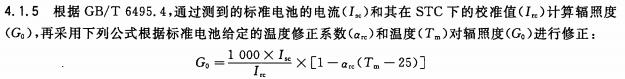
![]()
![]()

Photovoltaic devices - Part 10: Method for measuring linear characteristics (GB/T 6495.10-