The development method of the fixture 3D graphics library is to build a large number of common parts, fixture standard parts and parts graphics library of common parts of the enterprise under SolidWorks, and build the engineering database according to the data on the mechanical parts manual and the fixture design manual. On the basis of writing programs (such as VB, VC, Delphi, etc.), the API functions of SolidWorks are called to realize the size parameter driving of the library parts. 2.2 SolidWorks-based fixture assembly modeling method Previous page
The system can use the interactive method in the SolidWorks assembly environment, the part process drawing (3D model) of the jig to be designed as the basis of the assembly, according to the steps of manually drawing the fixture assembly drawing, interactively calling the positioning component in the fixture graphic library, Parts drawing of clamping elements and mechanisms, guiding element devices, etc. In the assembly modeling process, it is actually obtained from the secondary development, loaded in the menu item of the SolidWorks assembly generation environment, the size of the above components is driven, assembled, and finally the entire design is generated according to the overall layout of the fixture. Machine tool fixture assembly.
In the SolidWorks environment, assembly interference inspection and error analysis can be quickly performed on the fixture assembly, which greatly improves the efficiency. At the same time, the part model called in the fixture 3D graphics library can be analyzed by COS COSMOSX-press for stress analysis, and then converted to COSMOS/Works embedded in SolidWork: for more advanced finite element analysis. This allows for computer-aided design verification of the machine tool holder. The assembly can also use the plug-in Animator (animated software) that comes with Solidworks to simulate the motion of the fixture, that is, the motion mode and motion path of the movable parts in the fixture, so that the assembly can generate motion. Whether the part will produce motion interference so that it can be modified in time. Solidworks can generate AVI animation files for the motion process, and save it and run independently from the software environment.
In the 3D design environment SolidWorks, the specific design and assembly drawing design of the components are completed, and the assembly interference inspection and error analysis are performed, so that the correctness of the conceptual design can be verified, and errors and irrationalities in the conceptual design can be corrected. .
The detailed design is the final stage of the fixture design, and the main work is to complete the design of the two-dimensional graphics of the fixture. The current 3D design software SolidWorks has the ability to generate 2D work drawings from 3D, and has the ability to bidirectionally associate, and has 3D solid full size constraints and feature modification capabilities, so the size and shape can be modified in the design. 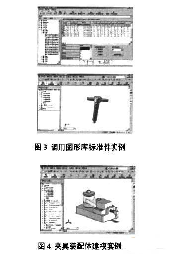
3. Application examples and conclusions
This paper presents a structural system of a three-dimensional CAFD system based on the SolidWorks platform. By establishing a three-dimensional graphics library for secondary development of SolidWorks, and the application method of SolidWorks in assembly modeling and analysis during fixture design, a CAFD system based on SolidWorks three-dimensional platform is proposed to effectively improve the efficiency and standard of fixture design. Sex. Figures 3 and 4 are examples of standard parts that call the 3D fixture graphics library and model examples of fixture assemblies generated under the SolidWorks assembly environment.
Continuously improve the fixture 3D graphics library established by SolidWorks secondary development can better meet the requirements of enterprises and improve the practicability and versatility of 3D CAFD system.
Research on 3D Fixture CAD System Based on SolidWorks(3)