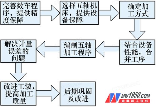
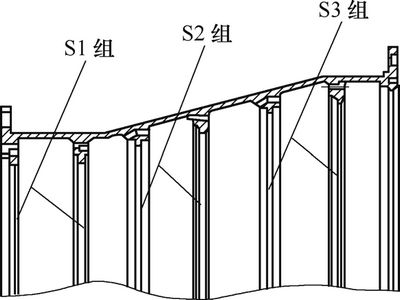
A certain type of turbine is an important part of the turbine part of a certain type of engine. The material is GH2132. The finished product is ring-shaped, with a large end diameter of 674.8 mm, a small end of f605.5 mm, a total length of 221.8 mm, an average wall thickness of about 2.8 mm, and three parts inside. Each group has 23 to 27 chutes with a width of 18 to 25 mm and a depth of about 2 to 6 mm. Due to the large space size, the processing and inspection processes are cumbersome. Involving more than 30 machining processes, it is easy to cause clamping and machining deformation during processing, and at the same time, the vibrating knife and the knife are serious, especially the processing of the gutter is more prominent. The gutters have been used for milling and milling for many years. The work steps are difficult, the process is cumbersome, the processing efficiency is low, and the product is out of tolerance, which seriously affects the processing quality. As the production volume continues to increase, it is necessary to further improve the processing capacity and ensure the smooth flow of its processes. The conversion of a turbine slot to a CNC milling is the most effective way to solve the above problems. This paper studies the CNC milling process of turbine gutters from the aspects of CNC milling process design, feed mode, feed volume adjustment, equipment selection, and improved measurement methods. Through the comprehensive analysis of the technical quality of existing products, combined with the ability of CNC milling equipment, the turbine grouting process was designed for CNC milling, as shown in Figure 1. (1) Analysis of equipment selection The factors affecting the production schedule are mainly in the two stages of several vehicles and milling. The process capability of several vehicles also restricts the milling process. The turbine program was optimized and improved, followed by a direct process shift to the milling process. The three sets of gutters for parts 740, 760, and 780 cannot be processed by ordinary numerical control equipment. Through the dimension data acquisition and process demonstration of a certain turbine, the equipment selection technology scheme is proposed: select a non-standard five-axis machining center with a numerical control indexing turntable and an angle head on the basis of the vertical machining center. (2) Improvement of the feeding method When the 530 milling process is repeated, the machine has an ellipse of about 0.15 mm, which is difficult to find and affects the positioning of the milling process of the gutter; the flatness of the rib ring in the gutter processing position, and the spacing of the ribs of each group of gutters The tolerance is large, which affects the positioning of the G54, G55 and G66 of the three sets of groove milling. At the same time, it is necessary to carry out repairs by continuously adding tools. According to the analysis, the 530 process size is 44±0.2mm, and the 5th-stage groove direction of f558~f623mm is a large section, which causes large-section stress accumulation, and the stress release in the subsequent process is obvious, resulting in poor flatness of the bearing surface and affecting the groove rib. The relative accuracy of the ring plane, and the number of empty knives in this process is too large, resulting in waste of resources and man-hours. The solution is proposed: the 80° external circular knife is replaced by a straight insertion, and the groove cutter of a width of 6 mm and R 0.8 mm is used instead of the R3mm round groove cutter (see Fig. 2). (3) Adjustment of feed rate The analysis considers that the feed rate of the machining program is unreasonable, which is one of the factors that cause the machining deformation of the parts. Therefore, the solution is proposed: the feed rate of each knife is adjusted from 0.2mm/r to 0.1 mm/r. (4) There are problems in the improvement of the tooling design: When the parts are processed by the clamping method of the spacers, several shortcomings are found: First, there are 8 supporting blocks under the clamps, because the turbines are not supported, the turbines are processed. Thin-walled parts, especially when machining the S3 group groove, have a large vibration, resulting in obvious vibration marks on the bottom of the groove. Secondly, due to design defects, the eight supporting blocks are easy to loose during the processing and easy to slide during the disassembly process, which affects the operation efficiency. Third, the fixture is poorly compatible when machining other parts. Tooling improvement program: design special tooling, make 8 separate blocks into integral annular blocks, the middle is made of aluminum alloy, and the contact surface with parts and faceplate is composed of two wear-resistant steel plates, steel plate It is connected with the aluminum alloy by screws. There are 8 screw pressing plates at the fitting side of the part, and a thick positioning circle is arranged in the ring. The above design is sufficient to solve the vibration knife caused by the point support. At the same time, it can be easily replaced to ensure the compatibility of other parts. ...... For more information, please download the attachment or view Metal Processing (Cold Processing), Issue 15, 2013: Pvc Roof Tiles,Plastic Roof Tiles,Synthetic Roof Tiles,Synthetic Glazed Roof Tile Shandong Gaoxin Chemical Co.,Ltd , http://www.gaoxinchem.com
China Southern Aviation Industry Group Co., Ltd. Liang Songshan 1. Number milling process design

2. Number milling processing technical solution


figure 2 
Figure 4 Turbine groove profile
Research on Machining Process of Aeroengine Turbine
